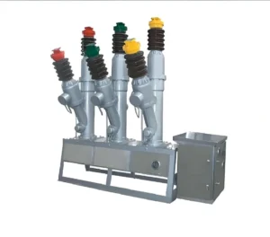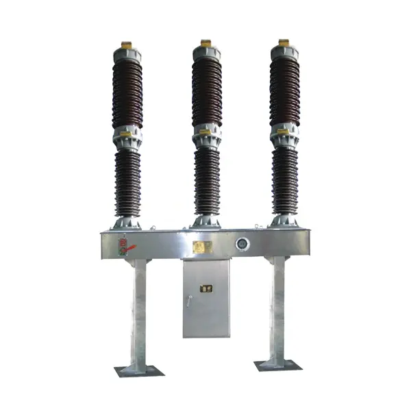
LW36-72.5/126 Outdoor High-Voltage Vacuum Circuit Breaker
LW36-72.5/126 Outdoor High-Voltage SF6 Circuit Breaker is designed for 72.5kV and 126kV AC power transmission and distribution systems. Using SF6 gas as the insulation and arc-extinguishing medium, it provides excellent breaking capability, reliable insulation performance, and long mechanical service life. The circuit breaker is widely used in substations, transmission networks, and grid protection applications, ensuring stable and safe operation in high-voltage power systems.
Get a QuoteOverview
The LW36-126 outdoor high-voltage SF6 circuit breaker is a three-phase AC 50Hz switching device designed for 126kV power transmission and transformation systems. It is mainly used for electrical equipment control, fault protection, and circuit switching operations, providing reliable performance for high-voltage grid applications.
Based on advanced thermal expansion combined with auxiliary gas flow arc-extinguishing technology, the LW36-126 is equipped with a reliable CTB-1 spring operating mechanism. The product is designed in accordance with GB1984-2003 AC High-Voltage Circuit Breakers and complies with the requirements of IEC 62271-100 High-Voltage AC Circuit Breakers, ensuring compatibility with international high-voltage equipment standards.
The self-energy arc-extinguishing system provides excellent interruption capability, short arcing duration, extended electrical endurance, and reduced operating noise. Using SF6 gas as the insulation and arc-extinguishing medium, the circuit breaker offers outstanding dielectric strength and reliable switching performance without combustion or explosion risks.
With its compact structure, simple operating mechanism, and high mechanical reliability, the LW36-126 provides a safe and efficient solution for substations, transmission networks, and other critical high-voltage power system applications.
Features
Product Structure and Operating Principle
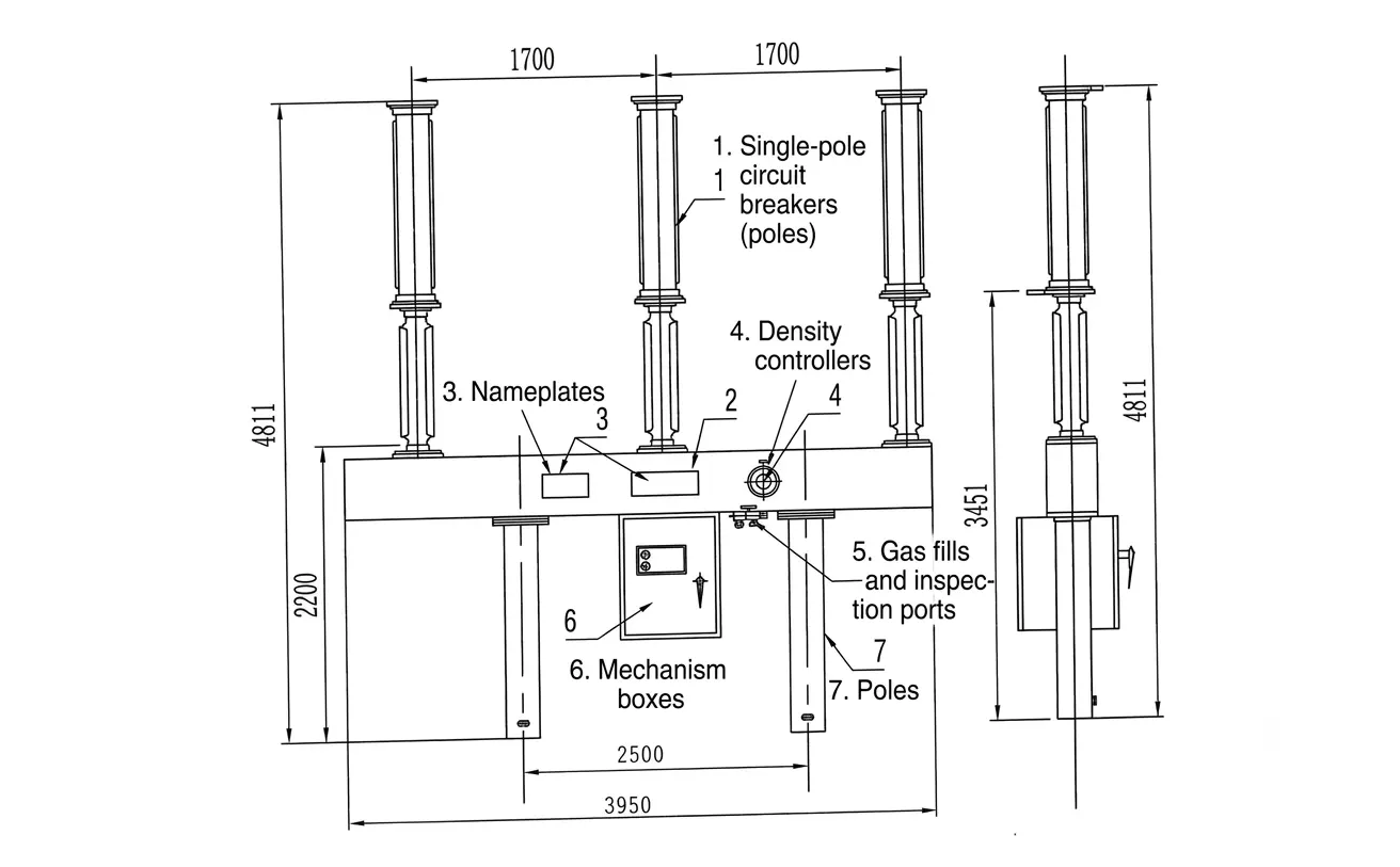
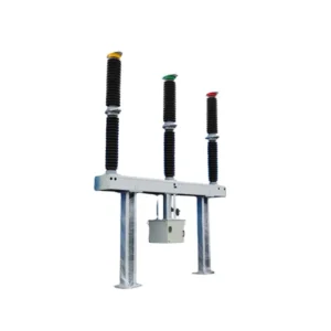
The LW36-126 SF6 circuit breaker adopts an integrated self-energy arc-extinguishing chamber design. Each phase consists of an independent single-column interrupter unit, referred to as a pole. The complete circuit breaker is composed of three poles installed on a common supporting frame.
The three poles are mechanically interconnected and driven by a spring operating mechanism, ensuring synchronized opening and closing operations. This configuration provides a simple structure, reliable mechanical transmission, and stable switching performance.
The upper section of each pole contains the ceramic housing of the arc-extinguishing chamber, while the middle section integrates the supporting porcelain insulator and the main frame structure. The operating mechanism box is mounted below the frame in a suspended arrangement, housing the spring operating mechanism and electrical control components.
The output connecting rod of the operating mechanism is linked to the operating arm, transmitting mechanical energy to the interrupter assembly to complete switching operations. A SF6 gas density monitoring controller is installed on the front side of the frame for real-time monitoring of gas conditions. The frame is supported by pillar insulators at both ends, providing mechanical stability and structural strength.
Electrical Control Configuration
The LW36-126 supports two types of electrical control configurations: single-break circuit control and double-break circuit control.
The standard electrical control diagrams and secondary wiring configurations may vary according to project requirements. The final control scheme is determined based on the technical agreement, and the corresponding electrical schematic and secondary wiring documents are supplied together with the equipment.
This flexible control design allows the circuit breaker to adapt to different substation configurations and application requirements.
Technical Data
| Item | Unit | Parameter | |
| Rated Voltage | kV | 126 | |
| Rated Current | A | 3150 | |
| Rated frequency | Hz | 50 | |
| Rated short-circuit breaking current | short-circuit current | kA | 31.5 |
| DC component | / | 40% | |
| Rated short circuit duration | s | 4 | |
| Rated for short-time withstand current | kA | 40 | |
| Rated short-circuit closing current (peak) | 100 | ||
| Rated peak withstand current | 100 | ||
| Rated 1min frequency withstand voltage (RMS) | Concerning the ground, between phases | kV | 230 |
| between contacts | 265 | ||
| Rated lightning impulse withstand voltage (peak) | Concerning the ground | 550 | |
| between phases | 650 | ||
| 5min zero gauge pressure withstand (RMS) | between contacts, concerning the ground | 95 | |
| Rated out-of-step breaking current | kA | IeX25% | |
| Near-area fault opening current | IeX90%,IeX75% | ||
| Rated line charging breaking current | A | 50 | |
| Rated sequence of operation | / | O-0.3s-CO-180s-CO | |
| First open pole factor | 1.5 | ||
| Closing time | ms | ≤100 | |
| Split time | 30≤t≤45 | ||
| breaking time | ≤60 | ||
| Opening and closing times | 60 | ||
| Opening synchronization | 4 | ||
| Closing synchronization | 5 | ||
| Rated SF6 gas pressure (20°C) | MPa | 0.6 | |
| Annual SF6 gas leakage rate | % | ≤0.5 | |
| Gas Moisture Content | ppm (v/v) | ≤150 | |
| radio interference level | μV | ≤2500 | |
| Mechanical life span | Times | 6000 | |
| Quality per breaker | kg | 1400 | |
| Mass of SF6 gas per unit | 6 | ||
| Main circuit resistance per pole | μΩ | 70 | |
Overall and mounting dimensions(mm)